
Search Our Database
How to Configure a Route-Based IPsec VPN Tunnel using the Custom Template in FortiGate via GUI
Introduction
Configuring a custom IPSec VPN in FortiGate via the Graphical User Interface (GUI) enables network administrators to establish a highly tailorable, encrypted tunnel between remote offices or client endpoints across the public internet. This custom configuration approach is ideal for complex network infrastructures requiring granular phase 1 and phase 2 proposal settings, non-standard encryption algorithms, or specialized routing options beyond basic wizards. Network administrators can perform this setup at any time directly through the FortiGate web console to maintain complete control over tunnel security parameters, ensure precise traffic selection, and protect internal corporate data.
Prerequisite
- Access to FortiGate GUI with Admin privilege
- Basic knowledge of IP networking, IPsec parameters (Phase 1 and Phase 2), and remote gateway details
- Basic understanding of FortiGate configuration steps, including creating a custom interface, setting up firewall policies, and configuring static routes
Step-by-step guide
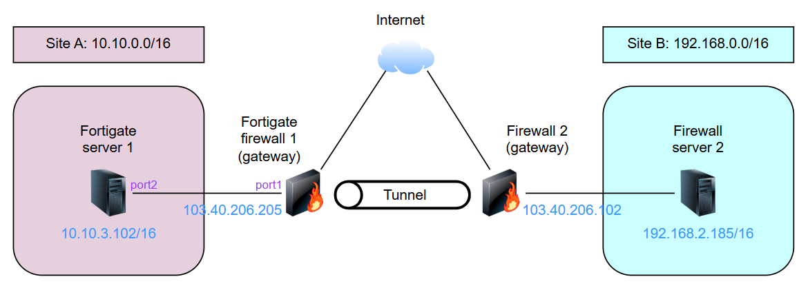
The diagram below illustrates the example IP addresses and interfaces used throughout this guide.
Step 1: Open IPsec Tunnel creation page
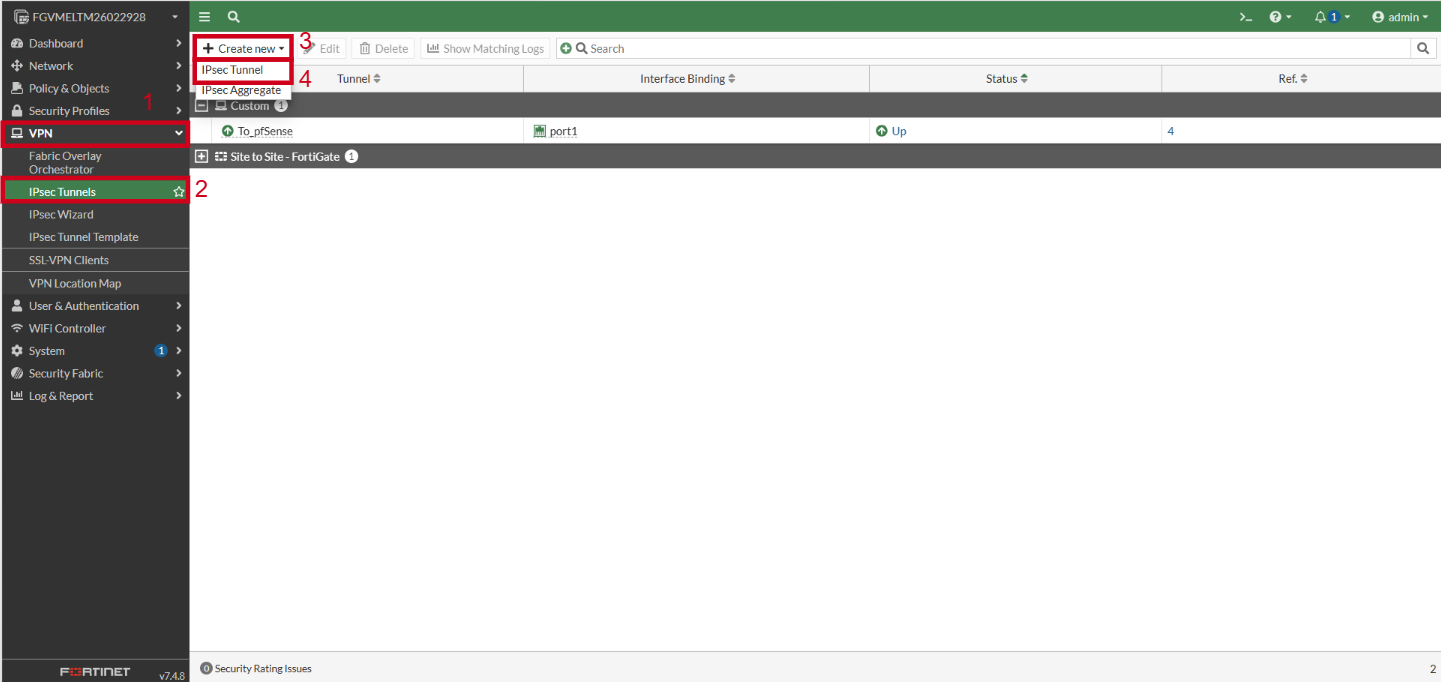
- Log in to your FortiGate GUI using administrator credentials.
- On the left navigation menu, click VPN and select IPsec Tunnels.
- Click Create new at the top menu bar to open the creation interface.
Step 2: Initialize custom template
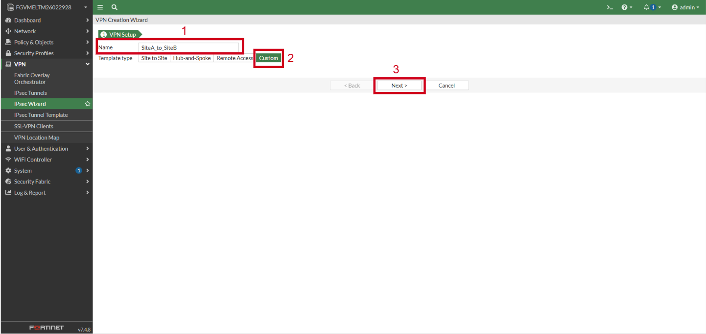
- In the Name field, enter a unique identification name for the VPN tunnel.
- Under Template type, select Custom.
- Click Next to proceed to detailed parameter configuration.
Step 3: Configure Network and Phase 1 parameters
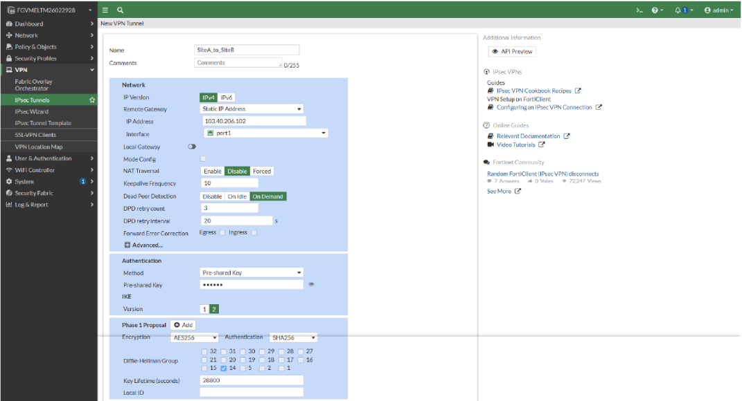
- Configure the following parameters:
- Network:
-
IP version: Choose IPv4.
-
Remote Gateway: Select Static IP Address.
-
IP Address: Enter the public IP address of Site B (for example, 103.40.206.102).
-
Interface: Select port1 (the WAN interface assigned to the public IP of Site A).
-
- Authentication:
-
Method: Select Pre-shared Key.
-
Pre-shared Key: Enter your secure key (ensure this matches the Pre-Shared Key configured on Site B).
-
IKE version: Select 2.
-
- Phase 1 Proposal
-
Encryption: Select AES256 (Choose at least 256 bits).
-
Authentication: Select SHA256 (Choose at least 256 bits).
-
Diffie-Hellman Group: Select 14 only.
-
Key Lifetime (seconds): Enter 28800.
-
- Network:
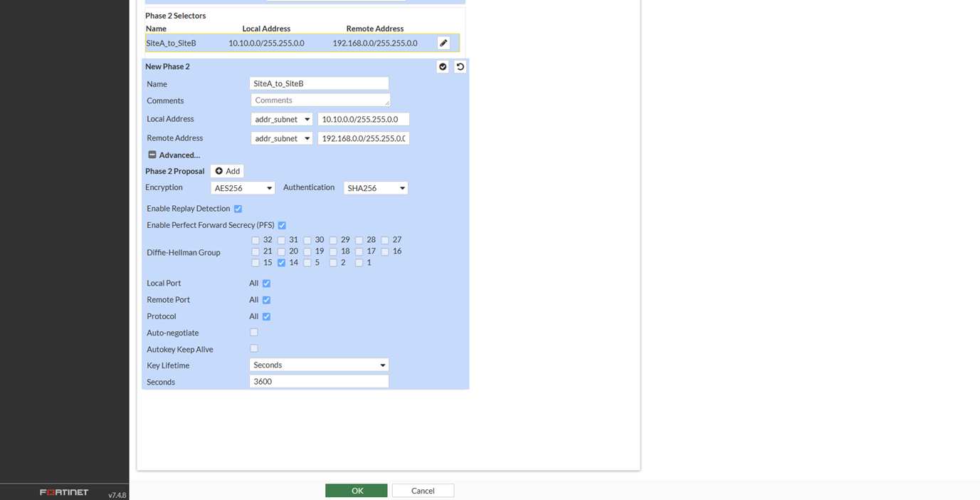
Step 4: Configure Phase 2 selectors
- Expand the Phase 2 Selectors section.
- Under New Phase 2:
- Local Address: Select addr_subnet and enter the local private subnet (for example, 10.10.0.0/255.255.0.0).
- Remote Address: Select addr_subnet and enter the remote private subnet (for example, 192.168.0.0/255.255.0.0).
- Under Advanced options (Phase 2 Proposal):
-
Encryption: Select AES256 (Choose at least 256 bits).
-
Authentication: Select SHA256 (Choose at least 256 bits).
-
Diffie-Hellman Group: Select 14 only.
-
- Click OK to save and finish creating the custom IPSec VPN entry.
Step 5: Configure the Static Route
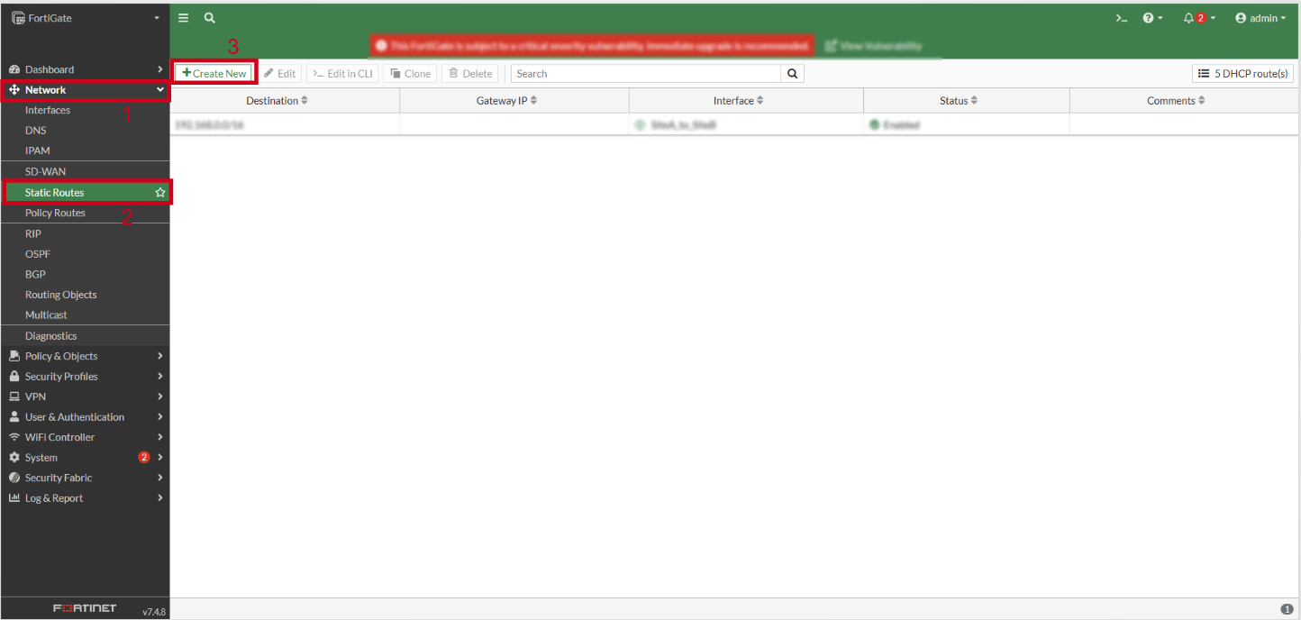
- Direct the remote network traffic into the VPN tunnel by adding a static route. Because this is a route-based VPN, the FortiGate uses this route to push traffic into the tunnel interface.
- Go to Network, select Static Routes and click Create New.
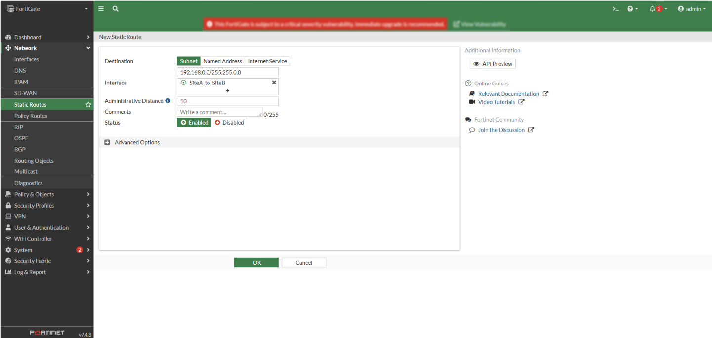
- Destination: Set to Subnet 192.168.0.0/16.
- Interface: Select the newly created SiteA_to_SiteB tunnel interface.
- Click OK.
Step 6: Configure Firewall Address Objects
- Create reusable address entries in the firewall to represent specific IP addresses, subnets, or address ranges. These objects can then be used in firewall policies to control and manage network access more easily.
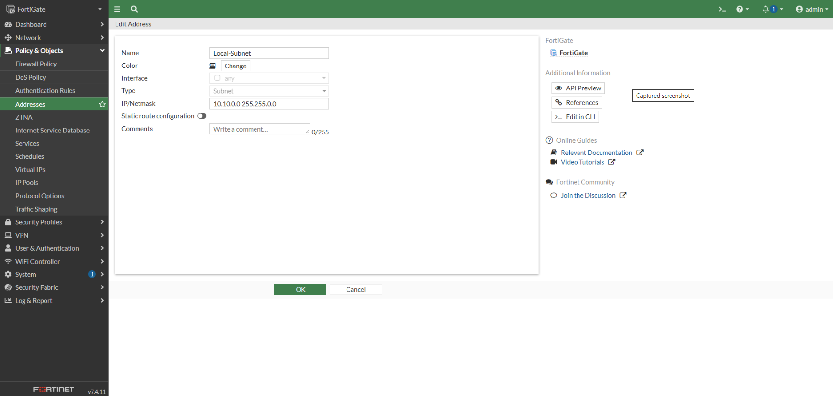
- Go to Policy & Objects, select Addresses and click on Create new.
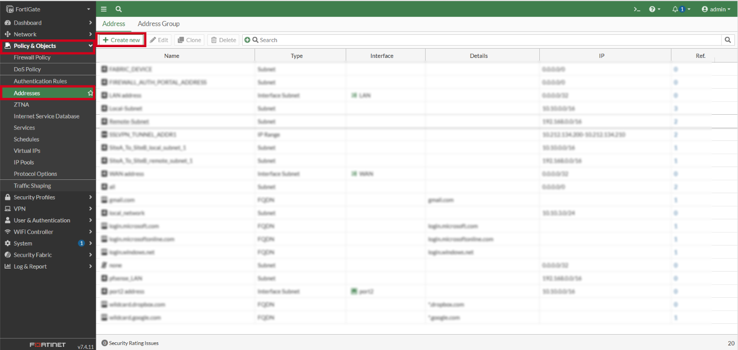
- Configure the following the parameters:
- Name: Local-Subnet
- IP/Netmask: 10.10.0.0 255.255.0.0
- Click OK to save the Address.
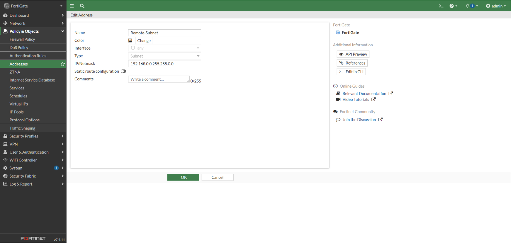
- Click again on the Create new to configure another Address.
- Name: Remote-Subnet
- IP/Netmask: 192.168.0.0 255.255.0.0
- Click OK to save the Address.
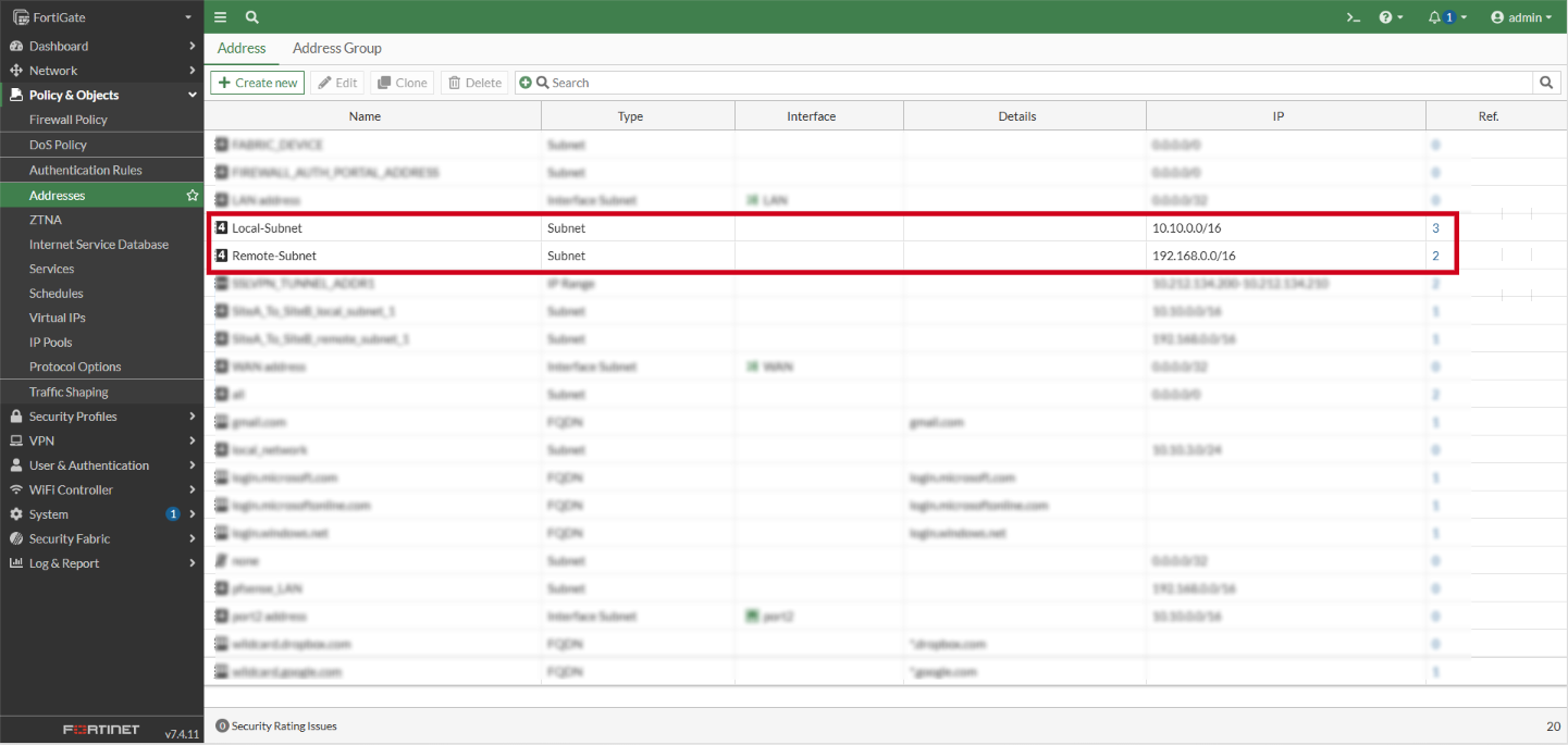
- Verify both addresses are created and appear in the Address page.
Step 7: Configure Firewall Policies
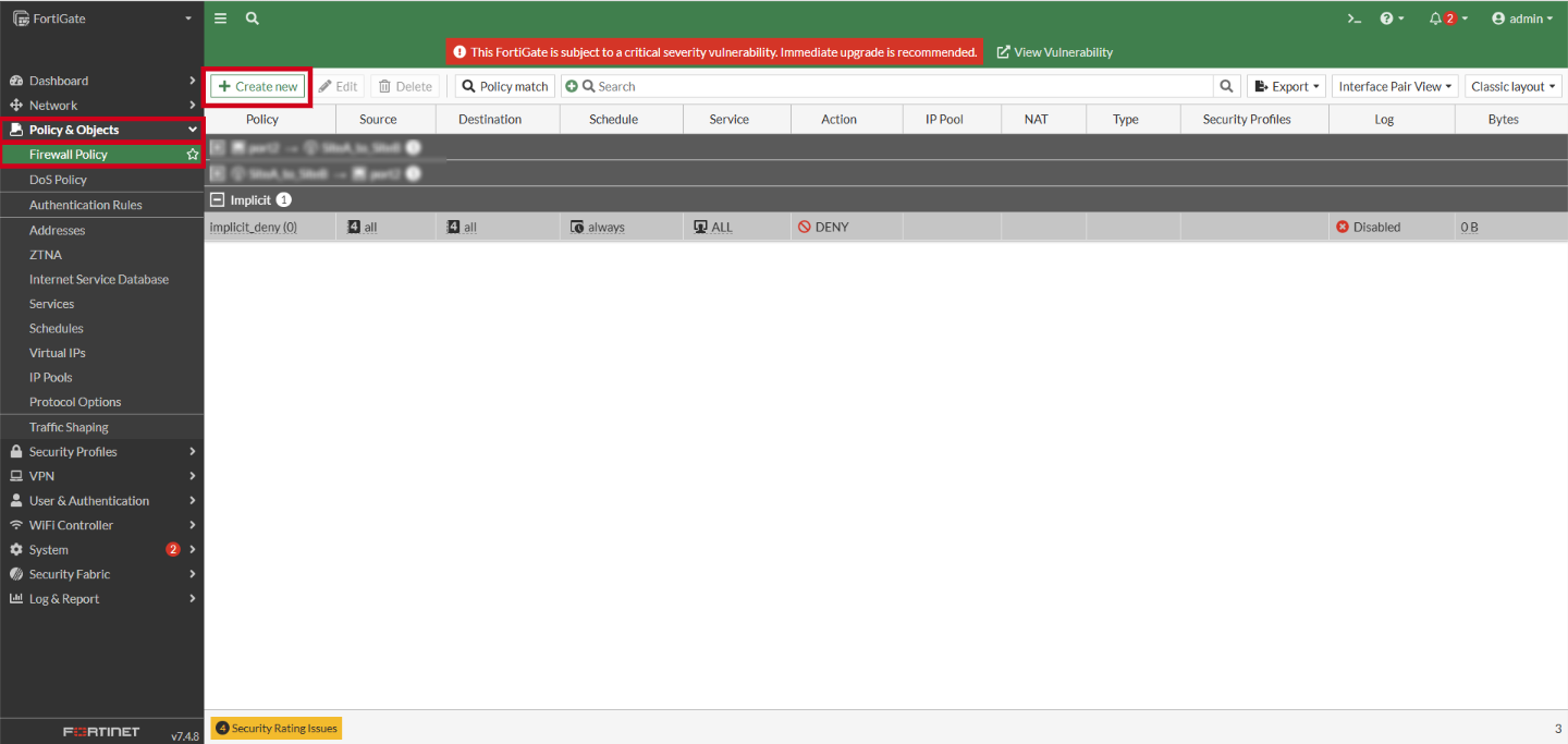
- Allow communication by creating firewall policies that permit traffic to flow bidirectionally between your local LAN and the VPN interface.
- Go to Policy & Objects, select Firewall Policy and click Create new.
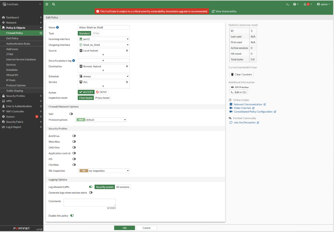
- Create Outbound Policy (Site A to Site B):
- Name: Allow-SiteA-to-SiteB
- Incoming Interface: port2 (LAN)
- Outgoing Interface: SiteA_to_SiteB (VPN Tunnel)
- Source: Local-Subnet (for example, 10.10.0.0/255.255.0.0)
- Destination: Remote-Subnet (for example, 192.168.0.0/255.255.0.0)
- Schedule: always | Service: ALL | Action: ACCEPT
- NAT: Select Disable (unless explicitly required by your topology). Click OK.
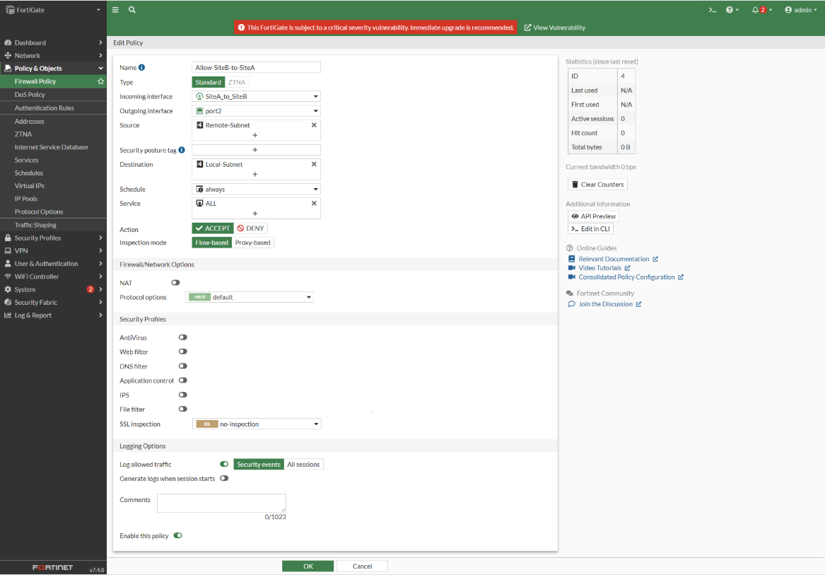
- Create Inbound Policy (Site B to Site A):
- Click Create New again to build the reverse policy.
- Name: Allow-SiteB-to-SiteA
- Incoming Interface: To_pfSense (VPN Tunnel)
- Outgoing Interface: port2 (LAN)
- Source: Remote-Subnet (for example, 192.168.0.0/255.255.0.0)
- Destination: Local-Subnet (for example, 10.10.0.0/255.255.0.0)
- Schedule: always | Service: ALL | Action: ACCEPT
- NAT: Select Disable (unless explicitly required by your topology). Click OK.
Step 8: Verify custom IPSec VPN tunnel state
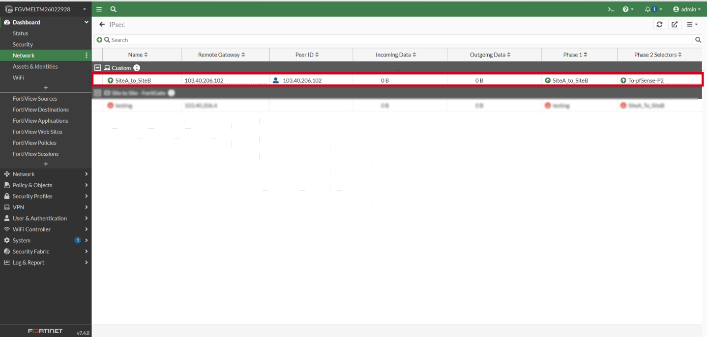
- Go to Dashboard and select Network to locate the IPsec widget.
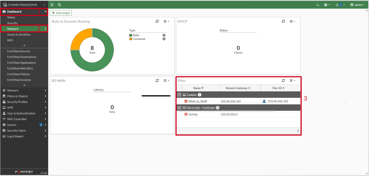
- Select your custom tunnel entry and click Bring Up to initiate tunnel negotiation.
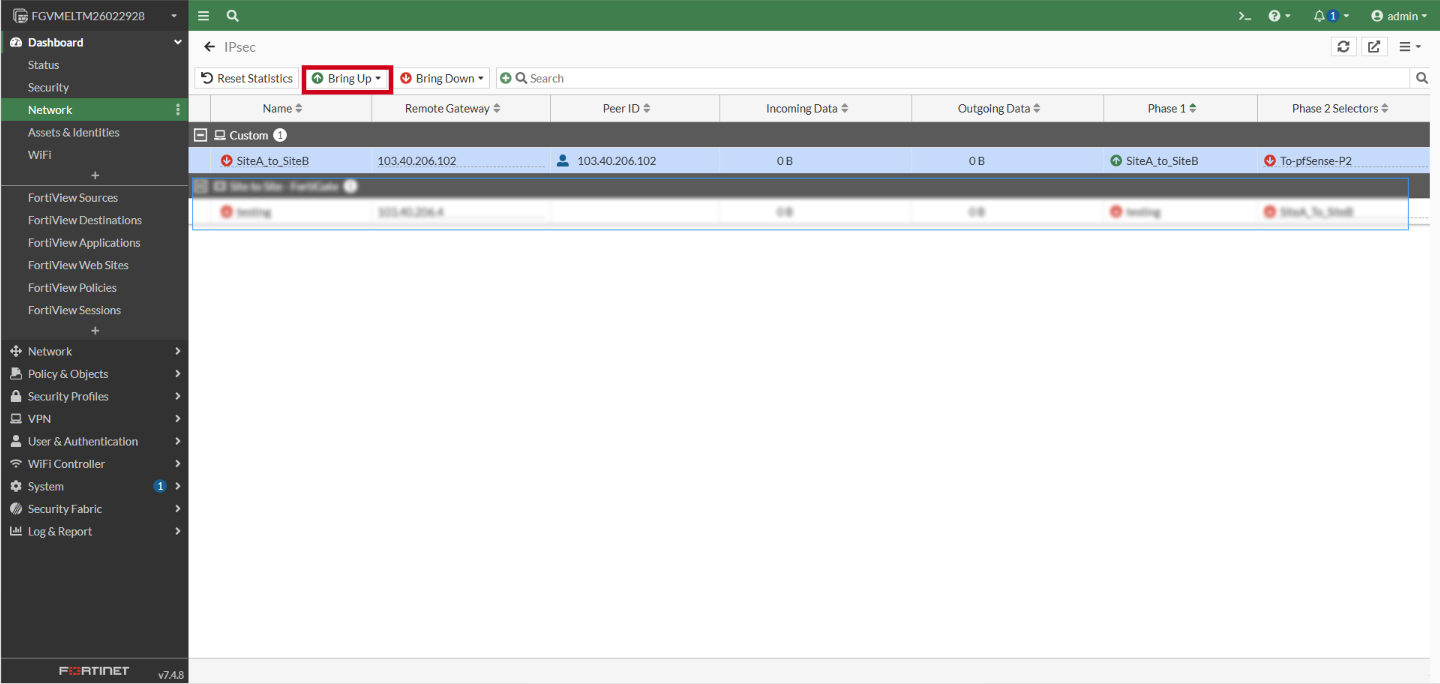
- Verify that Phase 1 and Phase 2 establish successfully with active status indicators.
Conclusion
By following this guidance, you can successfully set up a custom IPSec VPN in FortiGate via GUI to manage network traffic routing effectively.
For additional assistance or if you encounter any issues, please contact our support team at support@ipserverone.com.